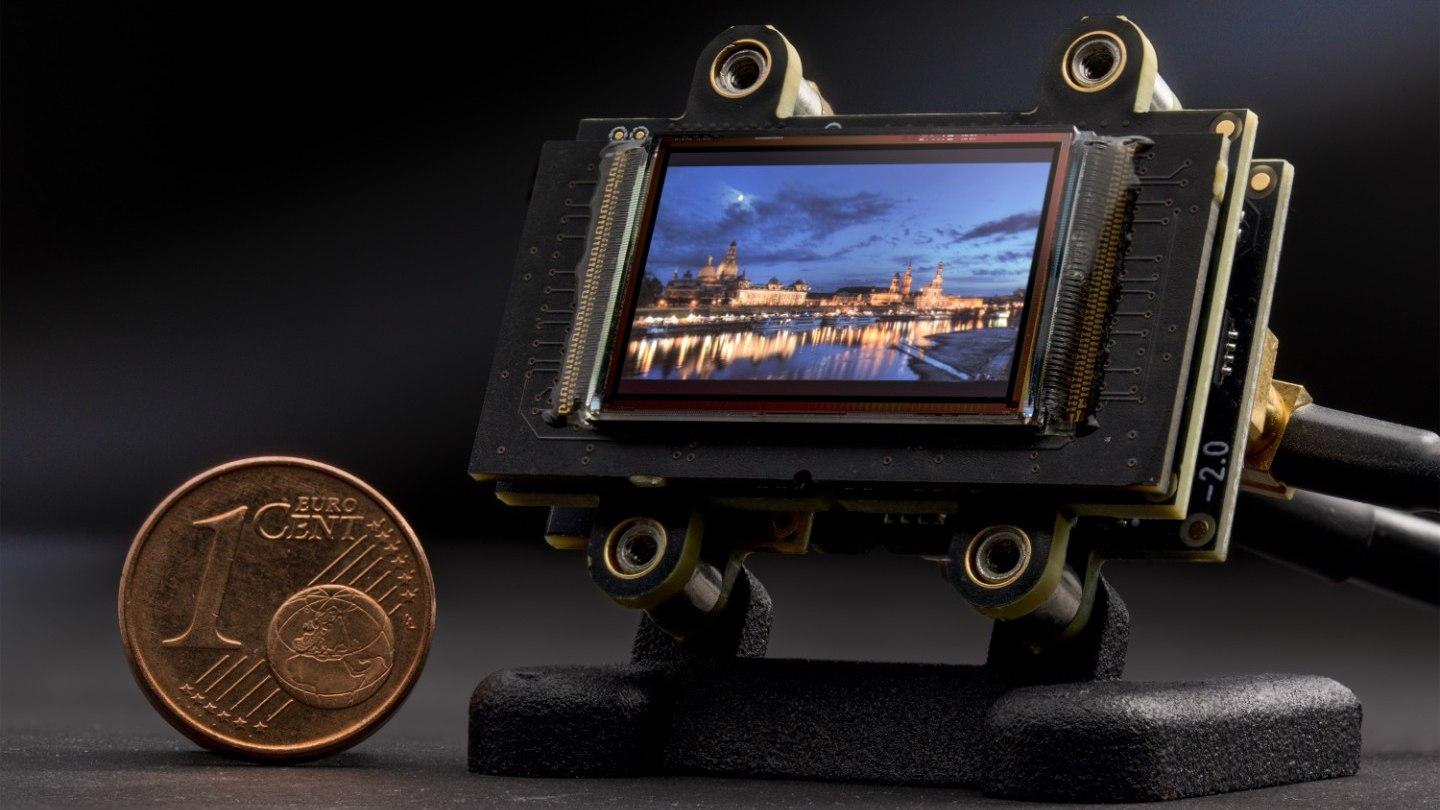
Researchers at the Fraunhofer Institute for Photonic Microsystems IPMS have developed a Universal Display Data Converter (UDDC). This enables the transfer of image data to existing Fraunhofer microdisplays from various input interfaces. The new UDDC will be presented for the first time at the joint booth of the Fraunhofer Society in Hall B4, Stand No. B-141, at electronica 2024 in Munich.
A data converter is an electronic circuit that transforms data from one form to another. Such converters are crucial for making different data formats compatible with various applications and systems.
Converting various standard video interfaces
The newly developed UDDC converts various standard video interfaces to a standard to drive various microdisplays and offers system developers and integrators adaption to video sources which are already available in their systems. This facilitates and accelerates the development of new products using Fraunhofer IPMS microdisplays in Augmented Reality (AR), Virtual Reality (VR), and other applications.
A Field-Programmable Gate Array (FPGA) serves as the central component of the system. The challenge in development was to create a system concept that allows maximum flexibility of the FPGA on the complex central system circuit board while occupying minimal space to simplify integration into prototype systems.
The microdisplays developed at Fraunhofer IPMS can now easily utilise established video protocols from the industry, including D-PHY+DSI from the MIPI Alliance in the mobile device sector (developed in the BMBF-funded project “EdgeVision”) and SMPTE SDI from the professional broadcasting area. The UDDC is also a universal and modular platform for easily adapting microdisplays to custom video protocols, such as those based on LVDS.
Structure of the UDDC
The UDDC is implemented through a stacked arrangement of multiple circuit boards. This allows an alternative video protocol to be used with minimal effort by combining a different selection of circuit boards. Alternatively, a custom protocol can be implemented with manageable effort since only a single circuit board with low complexity and firmware needs to be developed.
The circuit board stack includes the following boards:
1. Microdisplay with display circuit board
2. System circuit board with an FPGA for system initialisation, data conversion, and system management
3. Video input circuit board with a specific video connector (e.g., FPC-, coaxial, high-pincount micro-coaxial connectors, etc.), necessary components for operating the video interface, and a GPIO port for system configuration and status querying from external systems
4. Power supply circuit board including a connector supporting a wide voltage input and all necessary components for the system’s power supply
Advantages of the new UDDC
Florian Schuster, a scientist in IC and system design at Fraunhofer IPMS, explains the advantages of the new UDDC: “The flexible UDDC electronics platform allows for simply replacing the video input circuit board. In the simplest case, only replacing a connector for the respective video interface is necessary. Additionally, the overall system is only minimally larger than the microdisplay itself, making it easy to integrate into customer applications.”
In complex video protocols, adding additional video ICs may be necessary. In all cases, the circuitry for operating the most complex system component – the FPGA – remains unchanged. This means that the entire circuit board development effort for using an FPGA, such as creating the schematic and the intricate wiring of signals on the circuit board, is eliminated since the system circuit board can be used with any video input circuit board. The power supply circuit board can be universally used in all circuit board combinations.
The scientists are ready for custom adaptations of the microdisplays and now also the interfaces for use in new products.


